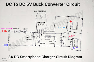
DC To DC 5V 3A Buck Converter Circuit Diagram, or 3A DC Smartphone Charger Circuit Diagram
DC To DC 5V 3A Buck Converter Circuit Diagram, or 3A DC Smartphone Charger Circuit Diagram. LM2576T-5.0, Battery mobile phone charger circuit board build; by "AMKP40 technology".
This is a very powerful DC to DC 5v buck Converter circuit using LM 2576T -5.0 switching step down voltage regulator IC this IC provide Max 3A output and produce low amount of heat comparing other linear voltage regulator, like LM317 or LM7805.
This circuit can charge your smartphone easily and very reliable to use, because in this IC have over voltage protection using feedback function inbuilt. You can drive this circuit any voltage between 7 Vot DC to 40 Volt DC this can still provide you 5 Volt DC in output.
If you have any questions about this circuit please feel free to comment below in the comment section.
Like 👍🏼 Share 👌 Comment 💌 SUBSCRIBE Follow 🔥
Thank you 🙏❤️❤️❤️
.


Comments
Post a Comment