Posts

Showing posts from December, 2023

Coil Less FM Transmitter Circuit Diagram. Long range FM transmitter. Without coil FM transmitter circuit diagram.

Image
 Diagram. Long range FM transmitter. Without coil FM transmitter diagram, designed by "AMKP40 technology". YouTube channel. Don't use any bench power supply for this Transmitter, use 3.7v battery only, otherwise this circuit may not work properly. For more information watch AMKP40 technology YouTube channel's videos. If you have any questions about this circuit please feel free to comment below in the comment section I will reply you rapidly if possible. Like 👍🏻 Share 📎 Comment 💌 Follow ✅ SUBSCRIBE 🔥 Thank you ❤️🙏🏻.

3.7V Lithium-ion battery charger with battery full indicator without IC

Image
How to make 3.7 volt Lithiun-ion Battery chager with full charged indicator without IC. By AMKP40 technology. This circuit work perfectly with 5V DC adapters and 3.7v lithium-ion battery. If battery is fully charged with 4.267v than RED LED turns off that means battery is fully charged. If you want fast charge your battery, you just change the resistor behind this diode. Also you can  adjust which voltage you want to show battery is fully charged, just rotating the 1K veriable resistor. This circuit Diagram is personal of AMKP40 technology [YouTube Channel]. If you have any questions about this circuit please comment below in the comment section.  Like 👍 Share 🙏 Comment 💬 and Subscribe our YouTube channel AMKP40 technology. Thank you ............................................................................

How To Make Good Quality 220vAC Automatic Night Light Circuit

Image
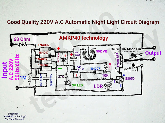
Good Quality 220V AC Automatic Night Light Circuit Diagram, or professional quality 220v AC automatic street light circuit diagram; by "AMKP40 technology". Friends this circuit is very good quality and reliable. This circuit operates in voltage between 150V A.C to 250V A.C in this voltage range this circuit works very well without any problems. And this capable wattage is approximately 500 watt Max. Parts List........ (1)= Vero Board (PCB) (2)= Two Pieces Male Connector (3)= A 12V Relay (4)= 5 pieces 1N4007 Diodes (5)= Two Film Capacitor 224K400V and 683K 275V You can only use 224K400V Film Capacitor. (6)= One 68 Ohm half watt resistor (7)= Other Resistors 1M one piece,27K Ohm one piece, 10K Ohm one piece, 150K Ohm one piece. (8)= 50K Variable resistor one piece. (9)= One 12V Zener Diode, use sufficient wattage. (10)= One 3V LED (11)= One S8050 NPN Transistor. (12)= One small LDR (13)= One 25V 220uF Electrolytic Capacitor, and One 50V 4.7uF Electrolytic Cap

Low battery cut-off circuit for 12v battery. Over discharge protection circuit for 12v battery.

Image
 Low battery cut-off circuit for 12v battery. Over discharge protection circuit for 12v battery.  Cut-Off Voltage 9.80v or less and Recovery Voltage is 10.00v or higher. DISADVANTAGES:-          [1] In this circuit's Relay consume power while circuit is on mode, but not consume power while circuit is off mode.          [2] Practically this circuit creates some problems when you use this circuit with a load and battery reached cut-off voltage level than the circuit cut-off the power, but after few seconds circuit automatically recovered and creates continuous ON/OFF fluctuations (small delay 2-4 second), because without load 12v batteries voltage (trickle voltage) jumps up from the cut-off voltage (9.80v) to recovery voltage (10.00v) and turns on the circuit which creates problems.            In future definitely I will try to improve the circuit. Still you can use this circuit with small load 10 watt to 15 watt. If you have any questions about this circuit please feel free to comme