Posts

Coil Less FM Transmitter Circuit Diagram. Long range FM transmitter. Without coil FM transmitter circuit diagram.

Image
 Diagram. Long range FM transmitter. Without coil FM transmitter diagram, designed by "AMKP40 technology". YouTube channel. Don't use any bench power supply for this Transmitter, use 3.7v battery only, otherwise this circuit may not work properly. For more information watch AMKP40 technology YouTube channel's videos. If you have any questions about this circuit please feel free to comment below in the comment section I will reply you rapidly if possible. Like 👍🏻 Share 📎 Comment 💌 Follow ✅ SUBSCRIBE 🔥 Thank you ❤️🙏🏻.

3.7V Lithium-ion battery charger with battery full indicator without IC

Image
How to make 3.7 volt Lithiun-ion Battery chager with full charged indicator without IC. By AMKP40 technology. This circuit work perfectly with 5V DC adapters and 3.7v lithium-ion battery. If battery is fully charged with 4.267v than RED LED turns off that means battery is fully charged. If you want fast charge your battery, you just change the resistor behind this diode. Also you can  adjust which voltage you want to show battery is fully charged, just rotating the 1K veriable resistor. This circuit Diagram is personal of AMKP40 technology [YouTube Channel]. If you have any questions about this circuit please comment below in the comment section.  Like 👍 Share 🙏 Comment 💬 and Subscribe our YouTube channel AMKP40 technology. Thank you ............................................................................

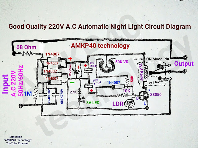
How To Make Good Quality 220vAC Automatic Night Light Circuit

Image
Good Quality 220V AC Automatic Night Light Circuit Diagram, or professional quality 220v AC automatic street light circuit diagram; by "AMKP40 technology". Friends this circuit is very good quality and reliable. This circuit operates in voltage between 150V A.C to 250V A.C in this voltage range this circuit works very well without any problems. And this capable wattage is approximately 500 watt Max. Parts List........ (1)= Vero Board (PCB) (2)= Two Pieces Male Connector (3)= A 12V Relay (4)= 5 pieces 1N4007 Diodes (5)= Two Film Capacitor 224K400V and 683K 275V You can only use 224K400V Film Capacitor. (6)= One 68 Ohm half watt resistor (7)= Other Resistors 1M one piece,27K Ohm one piece, 10K Ohm one piece, 150K Ohm one piece. (8)= 50K Variable resistor one piece. (9)= One 12V Zener Diode, use sufficient wattage. (10)= One 3V LED (11)= One S8050 NPN Transistor. (12)= One small LDR (13)= One 25V 220uF Electrolytic Capacitor, and One 50V 4.7uF Electrolytic Cap

Low battery cut-off circuit for 12v battery. Over discharge protection circuit for 12v battery.

Image
 Low battery cut-off circuit for 12v battery. Over discharge protection circuit for 12v battery.  Cut-Off Voltage 9.80v or less and Recovery Voltage is 10.00v or higher. DISADVANTAGES:-          [1] In this circuit's Relay consume power while circuit is on mode, but not consume power while circuit is off mode.          [2] Practically this circuit creates some problems when you use this circuit with a load and battery reached cut-off voltage level than the circuit cut-off the power, but after few seconds circuit automatically recovered and creates continuous ON/OFF fluctuations (small delay 2-4 second), because without load 12v batteries voltage (trickle voltage) jumps up from the cut-off voltage (9.80v) to recovery voltage (10.00v) and turns on the circuit which creates problems.            In future definitely I will try to improve the circuit. Still you can use this circuit with small load 10 watt to 15 watt. If you have any questions about this circuit please feel free to comme

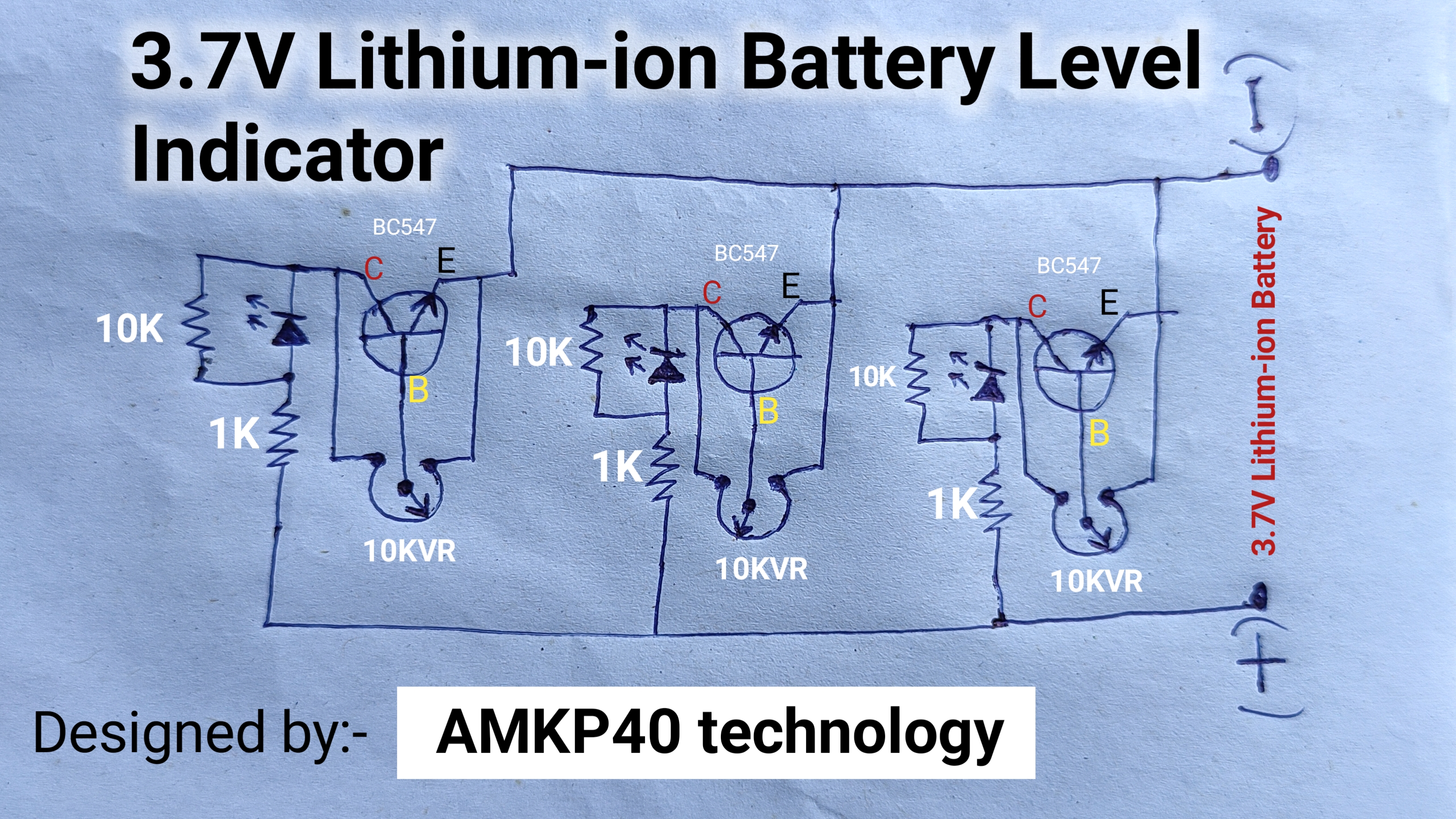
3.7v Lithium-ion Battery Charge Level Monitor Circuit Diagram

Image
 3.7v Lithium-ion Battery Charge Level Monitor Circuit Diagram; by "AMKP40 technology" YouTube Channel.  Without IC Narrow Voltage Range 3.7v Lithium-ion Battery (Adjustable) Charge Level Monitor. Battery charge status monitor circuit board.  YouTube Video Link   Like 👍🏻 Share 👌🏻 Comment 💌 SUBSCRIBE ✔️ Follow ✅ Thank you ❤️🙏🏻😊

Simplest delay off timer switch circuit diagram for 220v AC appliances.

Image
 Simplest delay off timer switch circuit diagram for 220v AC appliances. This circuit designed by "AMKP40 technology" YouTube channel's. This circuit designed for 2 minute 30 seconds delay off switch for 220vAC 400w maximum load (recommend). For more information visit AMKP40 technology YouTube channel. I you have any questions about this circuit please feel free to comment below in the comment section or visit AMKP40 technology YouTube channel. Like 👍🏻 Share 🔗 Comment 💌 Follow ✅ Subscribe ❤️🙏🏻💐💕💕💕🔥🇮🇳 .

How to make 12V 100Ah Automatic Battery Charger Circuit Diagram with Cut-Off and short-circuit protection

Image
 12V 100Ah/150Ah Automatic Battery Charger Circuit Diagram Invented and designed by AMKP40 technology. For more information please visit AMKP40 technology YouTube channel. Like 👍🏻 share 🔗 comment 💌 SUBSCRIBE and Follow ✅ Thank you ❤️🙏🏻

DC 12v High Ampere Constant Voltage Regulator circuit diagram.

Image
 DC 12v High Ampere Constant Voltage Regulator circuit diagram. High Current 12V DC Voltage Regulator Circuit Diagram. Like 👍🏼 Share 🔗 Follow ✅❤️ Subscribe "AMKP40 technology" YouTube channel. Comment your questions below 👇🏻 Thank you ❤️🙏🏻 .

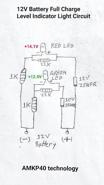
12V Car Battery Full Charge Level Indicator Light Circuit

Image
12v car battery full charge level indicator light circuit board; by "AMKP40 technology" YouTube channel. ★Red LED bulb start glowing at 14.1v or above. ★Green LED bulb start glowing at 12.5v or above. This circuit personal of "AMKP40 technology" YouTube channel's.   Like 👍🏼 Share 🔗 comment 💌 SUBSCRIBE AMKP40 technology YouTube channel. https://www.youtube.com/c/AMKP40technology  Thank you ❤️🙏🏻. .

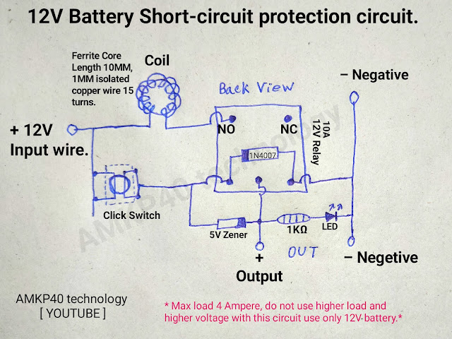
How To Make 12 Volt Battery Short-Circuit Protection Circuit with over discharge and overload protection circuit.

Image
 How To Make 12 Volt Battery Short-Circuit Protection Circuit with over discharge and overload protection circuit. This circuit developed by AMKP40 technology. 🔥⚙️Main Features Of This Circuit... (1) Short-Circuit Protection. (2) Over Discharge Protection [ Less than 7v DC this circuit turns OFF]. (3) Over Load Protection [it may not work properly]. This circuit working very perfectly with any 12V Battery.  IMPORTANT:– THIS CONSUME POWER WHILE CIRCUIT IS ON STATE. This circuit consume just little amount of power. ☝🏻☝🏻☝🏻☝🏻 Instead Of This Coil you can use ceramic resistor depending how much ampere you want to drive with this circuit, considering the Relay's Max Ampere rating. Know about this single pole double stroke 12v Relay. NO= Normally Open Pin, which not connected with any other pins until Relay not turns ON. NC= Normally Close Pin, which is connected with common pin of this circuit, until Relay turns ON.          And  Coil Pin-1 and Coil Pin-2 connected both each and oth

High Accuracy 12 Volt Battery Low Indicator Circuit Diagram.

Image
 High Accuracy 12 Volt Battery Low Indicator Circuit Diagram. If battery voltage less than 9.60 volt LED indicator start glowing. Circuit Diagram and designed by; "AMKP40 technology" YouTube channel. Friends this circuit working very well without a problem. This circuit's LED glowing if your 12v battery discharged at 0% battery level exactly 9.60v and stop glowing over 9.60v. Using this circuit diagram or design accuracy is approximately 5±% for more accuracy suggest you use TL471 IC etc. This circuit consume very low amount of power and you can use this circuit very wide voltage range DC- 3v to 30v maximum. IMPORTANT:- This circuit is very sensitive make sure perfect isolation the IC's gate pins.  If you have any questions about this circuit please feel free to comment below in the comment section below 👇🏻. Like 👍🏻 share 🔗 Follow ✅ SUBSCRIBE YouTube channel "AMKP40 technology". Thank you ❤️🙏🏻.

How to make simplest 220 volt AC automatic night light circuit using BT136 TriAC

Image
 Simplest 220 volt AC automatic night light circuit diagram; by "AMKP40 technology". Friends this circuit working very parfectly. This circuit is pre calibrated using 100 kilo Ohm ¼ watt resistor.  And one more important thing of this circuit's is, this circuit doesn't consume power when circuit is off mode. Follow my installation ideas. Keep your circuit with waterproof case. Keep the circuit always upper side from the bulb. Don't forget to do leakage proof lower side also. If you have any questions please feel free to comment below in the comment section. Like 👍🏼 Share 👌 Comment 💌 SUBSCRIBE ✅ AMKP40 technology YouTube channel. Thank you ❤️🙏🏻.

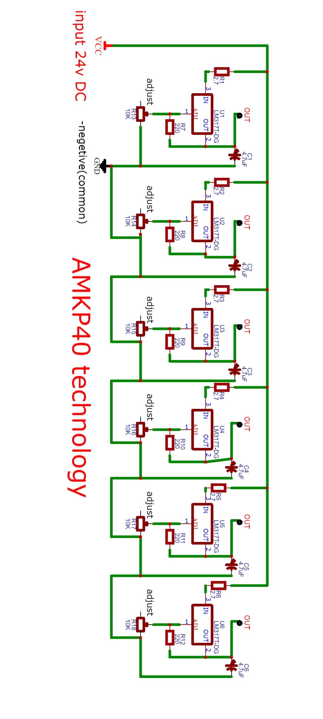
How to make multi variable dc power supply circuit

Image
 MULTI VARIABLE DC POWER SUPPLY CIRCUIT DIAGRAM by; "AMKP40 technology" YouTube. If you have any questions about this circuit please feel free to comment below in the comment section. Like 👍🏼 Share 👌 Comment 💌 SUBSCRIBE ✅ Follow 🙏🏻 Thank you....🙏🏻💌❤️

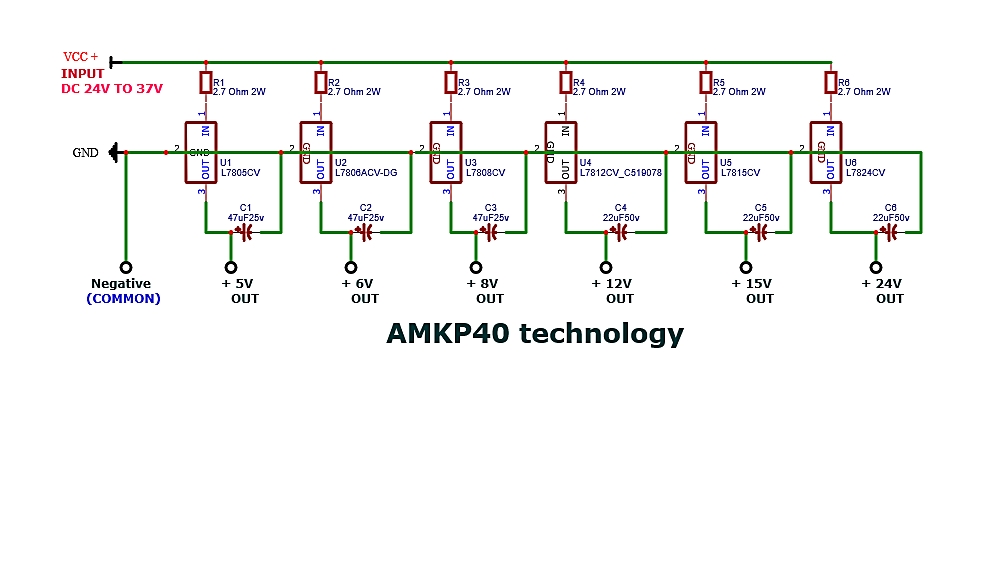
How to build multi output voltage dc power supply circuit which can provide 5v, 6v, 8v, 12v, 15v, 24v.

Image
Multi output voltage DC power supply circuit which can provide 5v, 6v, 8v, 12v, 15v, 24v 1 ampere; by "AMKP40 technology" YouTube channel. Friends this is a very simple DC 1A multiple output voltage power supply circuit.  If you have any questions about this circuit please feel free to comment below in the comment section. Like 👍🏼 Share 👌 Comment 💌 SUBSCRIBE ✅ Follow 🙏🏻 Thank you 😊❤️🙏🏻 .

How to make fixed frequency 108Mhz FM transmitter or Walkie talkie transmitter circuit diagram.

Image
 How to make a fixed frequency 108Mhz FM Transmitter Circuit or Simplest Walkie Talkie Transmitter Circuit at home; by "AMKP40 technology" YouTube. Friends this is a very simple stable frequency 108Mhz FM transmitter circuit diagram. In this circuit you can use 3.7V battery to 12V battery still perform this circuit fixed 108Mhz. If you use a 2N2219 transistor instead BC547 transistor you can get maximum range (approximately 300 meters) with a long antenna. You can build this circuit any structure or shapes without a problem. This circuit diagram is personal of "AMKP40 technology" YouTube channel's. If you have any questions about this circuit please feel free to comment below in the comment section. Like 👍🏼 Share 👌 Comment 💌 SUBSCRIBE ✅ Follow 🔥 Thank you 😊🙏🏻❤️ .

Simple and powerful 100W INVERTER circuit diagram.

Image
 Simple and powerful 100W 12V DC to 220AC INVERTER circuit diagram; by AMKP40 technology. Friends this is a very good lowest price powerful low frequency (60Hz) inverter circuit. This circuit very easy to build and pre-seted 60HZ frequency by two external resistor (10K,100K) and a film capacitor (333K400) if you want to change frequency just change the resistor 100K Ohm resistor. This circuit can provide 200W output power if you have a proper inverter transformer. This circuit's output frequency is square wave that doesn't mean you can't drive your home appliances, you can use every electrical appliances in this inverter's (100W) wattage range without a problem. In this circuit has two MOSFETS IRFZ44N you can use heat sink if you feel FETs are getting hot. If you have any questions about this circuit please feel free to comment below in the comment section.  Like 👍🏼 Share 👌 Comment 💌 SUBSCRIBE ✅ Follow 🔥 Thank you... 😊❤️🙏

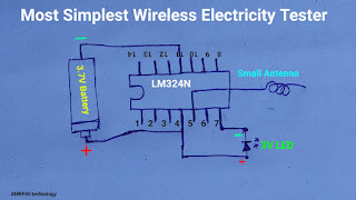
How to make most simplest wireless AC electricity tester circuit diagram

Image
 How to make most simplest wireless AC electricity tester circuit diagram using IC LM 324N ; by "AMKP40 technology" YouTube channel. Guys this is really amazing to build, because very very simplest anyone can make it easily.  If you have any questions about this circuit please feel free to comment below in the comment section. Like 👍🏼 Share 👌 Comment 💌 SUBSCRIBE 🙏 Follow 🔥 Thank you 🙏👍🏼❤️🌹

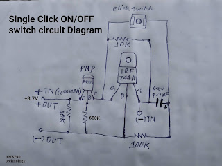
Single Click ON/OFF Latch switch circuit diagram, or single push button on/off circuit diagram

Image
 Single Click ON/OFF Latch switch circuit diagram, or single push button on/off circuit diagram; by "AMKP40 technology" YouTube channel. This circuit can work in 12V DC just small changes of resistors and adding a diode.  This circuit diagram is personal of AMKP40 technology YouTube channel's. Video Link- https://youtu.be/ZMDnTuH-eZM If you have any questions about this circuit please feel free to comment below in the comment section. Like 👍🏼 Share 👌 Comment 💌 SUBSCRIBE 🙏 Follow 🔥 Thank you...... 🙏🏻❤️

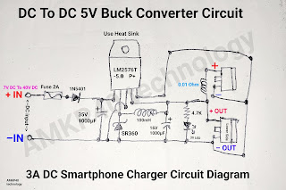
DC To DC 5V 3A Buck Converter Circuit Diagram, or 3A DC Smartphone Charger Circuit Diagram

Image
 DC To DC 5V 3A Buck Converter Circuit Diagram, or 3A DC Smartphone Charger Circuit Diagram. LM2576T-5.0, Battery mobile phone charger circuit board build; by "AMKP40 technology". This is a very powerful DC to DC 5v buck Converter circuit using LM 2576T -5.0 switching step down voltage regulator IC this IC provide Max 3A output and produce low amount of heat comparing other linear voltage regulator, like LM317 or LM7805. This circuit can charge your smartphone easily and very reliable to use, because in this IC have over voltage protection using feedback function inbuilt. You can drive this circuit any voltage between 7 Vot DC to 40 Volt DC this can still provide you 5 Volt DC in output. If you have any questions about this circuit please feel free to comment below in the comment section. Like 👍🏼 Share 👌 Comment 💌 SUBSCRIBE Follow 🔥 Thank you 🙏❤️❤️❤️ .